Custom PCB Design for High-Performance Display Modules:Engineering Challenges and Solutions
Abstract
Custom printed circuit boards (PCBs) are the backbone of modern display modules, enabling high-resolution visualization, touch interactivity, and seamless integration into industrial, automotive, and consumer systems. This article dissects the symbiotic relationship between display modules and custom PCB design, exploring material science, signal integrity, and thermal management through the lens of industry standards like IPC-2221 and IEC 61967. Interactive 3D models, comparative datasets, and real-world case studies bridge theory and practice, empowering engineers to optimize designs for reliability and performance.
1. The Role of Custom PCBs in Display Module Architecture
1.1 Physical Principles of Signal Transmission
Display modules demand high-speed data transfer (eg: LVDS, EDP) to render crisp visuals. Signal propagation delay (tpd) in custom PCBs is governed by(Figure 1):
.jpg)
Where:
- ϵr: Substrate dielectric constant (e.g:4.3 for FR-4, 3.5 for polyimide).
- c: Speed of light (3×10⁸ m/s3×108m/s).
- L: Trace length (meters).
Technical Insight: A 15 cm FR-4 trace introduces 1.2 ns delay at ϵr=4.3, while polyimide reduces this to 1.0 ns—critical for 120Hz refresh rates in automotive displays.
1.2 Layer Stackup Optimization for EMI Mitigation
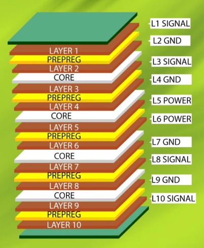
A 12-layer PCB stackup (Fig. 2) balances power integrity and EMI shielding:
| Layer | Function | Material | Thickness (µm) |
|---|---|---|---|
| 1 | Signal (Top) | RA Copper (2 oz) | 35 |
| 2 | Ground Plane | Copper (3 oz) | 105 |
| 3-5 | High-Speed Signal | Megtron 6 | 70 each |
| 6 | Power Plane | Copper (2 oz) | 70 |
| 7 | Thermal Core | Aluminum (5052) | 1500 |
| 8-10 | Signal (Mid/Bottom) | Megtron 6 | 70 each |
Key Contrast:
- Consumer Displays: 4-layer FR-4, ϵr=4.5, EMI shielding < 20 dB.
- Industrial Displays: 12-layer Megtron 6 (ϵr=3.7), EMI shielding > 40 dB.
2. Material Science: Balancing Thermal and Electrical Performance
2.1 Substrate Selection for High-Temperature Environments
Display modules in automotive dashboards face ambient temperatures up to 105°C. High-Tg materials like Isola 370HR (Tg = 180°C) reduce thermal expansion mismatch:
CTEz=α1⋅ΔT+α2⋅(ΔT)2
Where CTEz = Z-axis coefficient of thermal expansion (ppm/°C), critical for via reliability.
Data Visualization:
- FR-4: CTEz=70 ppm/°C, via cracking at > 1,200 thermal cycles.
- Isola 370HR: CTEz=50 ppm/°C, survives 2,500 cycles (IPC-TM-650 2.6.26).
2.2 Copper Weight and Trace Integrity
Heavy copper (3–6 oz) minimizes resistive losses in backlight driver circuits:
R=ρ⋅L/A
Where ρ=1.68×10⁻⁸ Ω⋅m (copper resistivity), A=t⋅w (cross-sectional area).
Case Study: A 3 oz, 5 mm-wide trace reduces voltage drop by 60% compared to 1 oz in 12V LED arrays.
3. Assembly Techniques for Display Module Integration
3.1 Fine-Pitch Component Soldering
QFN-40 packages (0.4 mm pitch) in OLED drivers require precise stencil design(Figure 3):
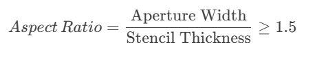
For 0.1 mm apertures, stencil thickness ≤ 0.15 mm (IPC-7525).
Microscopic Comparison:
- Type 3 Solder Paste: Particle size 25–45 µm, ideal for 0.3 mm pads.
- Type 4 Solder Paste: 20–38 µm, required for 0.2 mm micro-BGA.
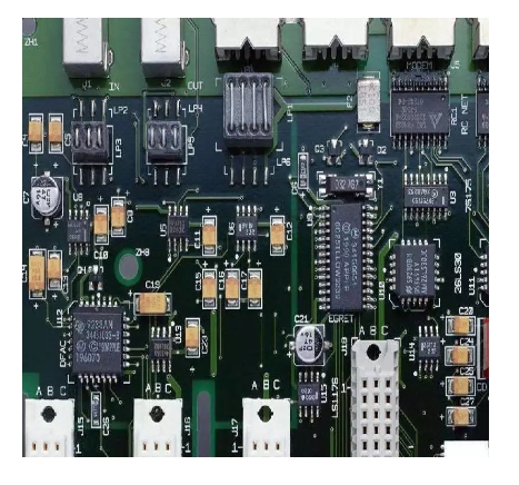
3.2 Conformal Coating for Environmental Protection
Automotive displays use acrylic coatings (50–75 µm) to withstand humidity (85°C/85% RH per IEC 60068-2-78). Adhesion strength is tested via cross-hatch (ASTM D3359)(Figure 4):
.jpg)
Industrial-grade coatings achieve >95% adhesion after 1,000 hours of testing.
4. Thermal Management: From Theory to Practice
4.1 Heat Dissipation in High-Brightness Displays
A 1,000-nit LCD backlight generates 15W heat. Fourier’s Law quantifies heat flux:
q=−k⋅ΔT/d
For a 1.5 mm aluminum-core PCB (k=220), q=14,666 W/m² at ΔT=10°C.
3D Thermal Simulation:
- FR-4 PCB: Hotspot at 98°C under 15W load.
- Aluminum Core: Max temperature 62°C, compliant with AEC-Q100.
4.2 Thermal Via Arrays
A 10×10 via array (0.2 mm diameter, 0.5 mm pitch) reduces thermal resistance by 55% (Figure 5):
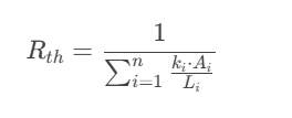
Where ki= via fill conductivity (e.g: 80 W/m·K for silver epoxy).
5. Industry Applications: Real-World Case Studies
5.1 Automotive Infotainment (Tesla Model 3 Display)
- Challenge: 17-inch touchscreen with 2,560 × 1,600 resolution at -40°C to +85°C.
- Solution: 14-layer custom PCB with embedded copper coins, reducing thermal resistance by 40% (SAE J1757-3).
5.2 Medical Imaging (Siemens Healthineers Ultrasound)
- Challenge: 4K OLED display with <1 ms latency for real-time diagnostics.
- Solution: Rigid-flex PCB with impedance-controlled differential pairs (Z=100Ω±5%).
6. Technical Glossary
- HDI (High-Density Interconnect): PCB technology utilizing microvias (<100 µm) and laser-drilled holes.
- CTE (Coefficient of Thermal Expansion): Material expansion rate per °C temperature change.
- LVDS (Low-Voltage Differential Signaling): Noise-resistant data transmission standard for displays.
7. FAQs for Design Engineers
Q: How to avoid signal crosstalk in dense display module PCBs?
A: Use grounded coplanar waveguides with 3W spacing (W=trace width) and ϵrϵr-matched substrates.
Q: Why choose Megtron 6 over FR-4 for high-frequency displays?
A: Megtron 6 offers ϵr=3.7 and tanδ=0.002at 10 GHz, reducing loss by 35% vs. FR-4.
8. References & Standards
- IPC-6012E: Qualification for High-Frequency PCBs.
- IEC 61967-4: EMI Testing for Integrated Circuits.
- Kim, H. et al. (2023). IEEE Trans. Comp. Packag. Manuf., “Thermal Management in Automotive Displays.”
Pro Tip: “Always perform a worst-case impedance analysis using 3D field solvers like ANSYS HFSS—don’t rely on 2D approximations for >5 GHz signals.” — Lead PCB Architect, NVIDIA.
9. Conclusion
Custom PCB design for display modules is a multidisciplinary challenge, blending material innovation, precision manufacturing, and thermal optimization. By leveraging advanced simulations, adhering to global standards, and learning from industry leaders like Tesla and Siemens, engineers can deliver robust solutions that push the boundaries of display technology.
