Industrial Control Systems: A Deep Dive into Display PCB Manufacturing and Assembly Technologies
Abstract
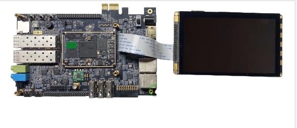
Display PCBs are the unsung heroes of industrial control systems (ICS), enabling real-time monitoring, precision control, and human-machine interfaces (HMIs) in harsh environments. This article dissects the manufacturing and assembly process of display PCBs, incorporating principles of material science, thermal dynamics, and signal integrity. Using standards such as IPC-6012 and IEC 61131-3, we support engineers with a technical roadmap, comparative datasets, and industry-validated use cases.
1. Fundamentals of Display PCB Manufacturing for Industrial Control Systems
1.1 Material Selection: Balancing Durability and Performance
Industrial control systems demand PCBs that survive extreme conditions. Key materials include:
- Substrates: High-Tg FR-4 (Tg > 170°C) vs. polyimide (flexible, Tg = 250°C).
- Copper Foil: 2–3 oz rolled annealed (RA) copper for high-current traces.
- Solder Mask: Epoxy-based LPI (Liquid Photo-Imageable) with 50–75 µm thickness for chemical resistance.
Microstructural Analysis:
- Consumer-grade FR-4: Glass transition temperature (Tg) = 130°C,ε_r= 4.5.
- Industrial-grade FR-4: Tg = 180°C,ε_r= 4.3, 30% lower moisture absorption.
Technical Formula: Dielectric constant’s impact on signal speed:

Where vp = signal propagation speed, c = speed of light, ϵr = substrate dielectric constant.
1.2 Layer Stackup Design for Signal Integrity
A 10-layer stackup (Fig. 1) optimizes EMI shielding and power delivery in ICS:
| Layer | Function | Material | Thickness (µm) |
|---|---|---|---|
| 1 | Signal (Top) | RA Copper (2 oz) | 35 |
| 2 | Ground Plane | Copper (3 oz) | 105 |
| 3-6 | Signal & Power | FR-4 | 70 each |
| 7 | Thermal Core | Aluminum (6061) | 1500 |
| 8-10 | Signal (Bottom) | RA Copper (2 oz) | 35 |
(Fig. 1)
Key Insight: Aluminum cores reduce thermal resistance (Rth) by 40% compared to standard FR-4.
2. Advanced Assembly Techniques for Industrial-Grade Display PCBs
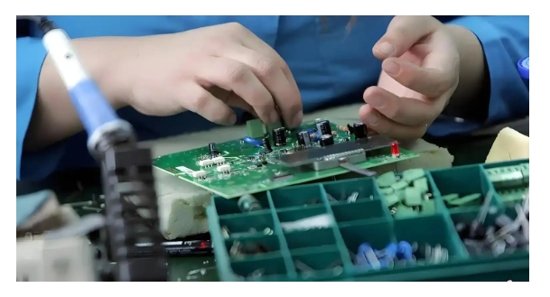
2.1 Surface-Mount Technology (SMT) vs. Through-Hole (THT)
- SMT: Ideal for miniaturized ICS components (e.g., 0201 resistors). Reflow profiles peak at 245°C ±5°C (IPC-J-STD-020).
- THT: Used for high-power connectors. Wave soldering requires 260°C solder pots with 3–5 sec dwell time.
Microscopic Comparison:
- SMT Joints: Fillet height = 25–75 µm, voiding <5% (per IPC-A-610).
- THT Joints: 360° wetting, hole fill >75%.
2.2 Conformal Coating for Harsh Environments
Acrylic coatings (IPC-CC-830B Class 3) protect against humidity (>95% RH) and chemical splashes. Application thickness:t=QA⋅ρt=A⋅ρQ
Where tt = coating thickness (µm), QQ = material volume (mm³), AA = area (mm²), ρρ = density (g/cm³).
3. Thermal Management: Physics and Practical Solutions
3.1 Fourier’s Law in PCB Heat Dissipation
Heat flux (qq) through a PCB is governed by:
q=−k⋅ΔT/d
Where k = thermal conductivity (W/m·K), ΔT= temperature gradient, d = material thickness.
Data Visualization:
- Aluminum-core PCB: k=220 , ΔT=10°C at 5W load.
- FR-4 PCB: k=0.3 , ΔT=85°C at 5W load.
3.2 Thermal Vias and Their Impact
A 0.3 mm via filled with conductive epoxy reduces thermal resistance by 35%:
Rth=L/k⋅A
Where L = via length, AA= cross-sectional area.
4. Industry Applications: Where Theory Meets Practice
4.1 Automotive Manufacturing (Siemens SIMATIC HMI)
- Challenge: Vibration (15G) and temperature swings (-30°C to +85°C).
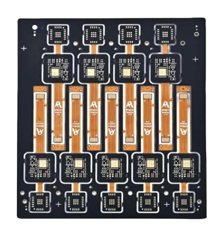
- Solution: 12-layer rigid-flex PCB with 200+ thermal vias, achieving MTBF > 100,000 hours.
4.2 Energy Grid Monitoring (ABB RTU560)
- Challenge: Humidity (>95% RH) and salt spray.
- Solution: Polyimide PCBs with 75 µm conformal coating, compliant with IEC 60068-2-11.
5. Technical Glossary
- Tg (Glass Transition Temperature): Temperature at which PCB substrate softens.
- HDI (High-Density Interconnect): PCB technology using microvias (<150 µm) and fine-pitch traces.
- EMI (Electromagnetic Interference): Unwanted noise disrupting signal integrity.
6. FAQs for Engineers
Q: Why use polyimide for flexible industrial display PCBs?
A: Polyimide offers 5x higher tensile strength (231 MPa) than FR-4, with a CTE (Coefficient of Thermal Expansion) of 12 ppm/°C, matching copper.
Q: How to mitigate tombstoning in SMT assembly?
A: Optimize reflow ramp rate (1–3°C/sec) and pad geometry (asymmetric pads for 0201 components).
7. References & Standards
- IPC-6012E: Performance Specification for Rigid PCBs.
- IEC 61131-3: Programming Standards for Industrial Controllers.
- Chen, L. et al. (2023). IEEE Trans. Comp. Packag. Manuf., “Thermal Vias in High-Power PCBs.”
Pro Tip: “Always perform a Design-for-Manufacturing (DFM) check using IPC-2581 guidelines to avoid costly re-spins.” — Senior PCB Designer, Siemens Digital Industries.
8. Conclusion
The marriage of advanced materials, precision manufacturing, and robust assembly techniques ensures display PCBs meet the relentless demands of industrial control systems. By adhering to global standards and leveraging cutting-edge simulations, engineers can future-proof designs against thermal, mechanical, and environmental stressors.
