Explore LED PCB
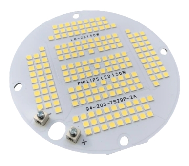
LED PCB (Light Emitting Diode Printed Circuit Board) is a type of printed circuit board specifically designed for LED lighting devices, widely used in LED lamps, displays, and backlight modules. This article will delve into the physical principles, material selection, design principles, and practical applications of LED PCBs, helping engineers and technical professionals gain a deeper understanding of the core technologies behind LED PCBs.
Glossary of Terms
- LED: Light Emitting Diode.
- PCB: Printed Circuit Board.
- MCPCB: Metal Core Printed Circuit Board.
- FR4: A common material for circuit boards.
- Copper Foil: A thin sheet of copper.
- Thermal Conductivity: The ability of a material to conduct heat.
- Joule Heating: Heat generated by electric current passing through a resistor.
Physical Principles and Mechanisms
The core of an LED PCB lies in its ability to efficiently manage heat and current. The efficiency and lifespan of an LED, as a semiconductor device, are closely related to its operating temperature. According to Joule’s Law, the heat generated by current passing through an LED can be expressed as:
Q=I2⋅R⋅tQ=I2⋅R⋅t
where Q:Q is the heat generated, I:l is the current, R:R is the resistance, and t:t is the time.
To effectively dissipate heat, LED PCBs often use metal-core substrates (MCPCB), which have a thermal conductivity of up to 200 W/m·K, significantly higher than that of standard FR4 material, which is only 0.3 W/m·K.
Material Selection and Design Principles
1. Substrate Selection
The choice of substrate for an LED PCB directly impacts its thermal management performance. Common substrates include:
- FR4: Low cost but low thermal conductivity, suitable for low-power LED applications.
- MCPCB: High thermal conductivity, suitable for high-power LED modules.
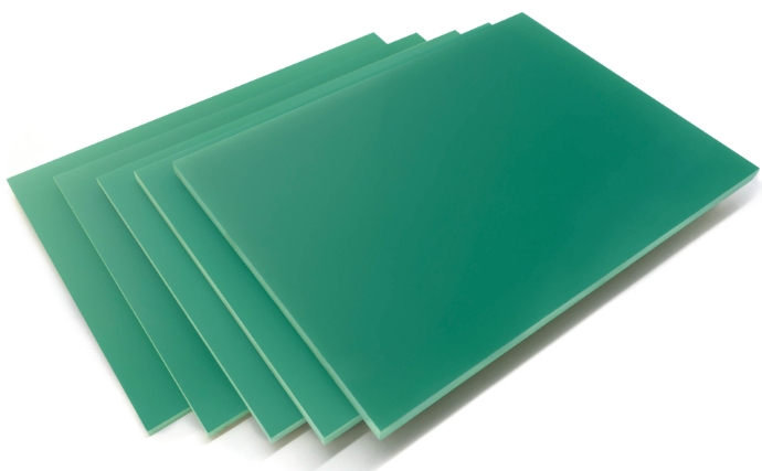
The picture above is FR4 material, which is used to make PCB
2. Copper Foil Thickness
The thickness of the copper foil determines the current-carrying capacity of the circuit board. According to IPC standards, copper foil thickness is typically measured in ounces (oz):
1oz=0.035mm1oz=0.035mm
For high-power LED applications, it is recommended to use 2 oz or thicker copper foil to reduce resistance and heat generation.
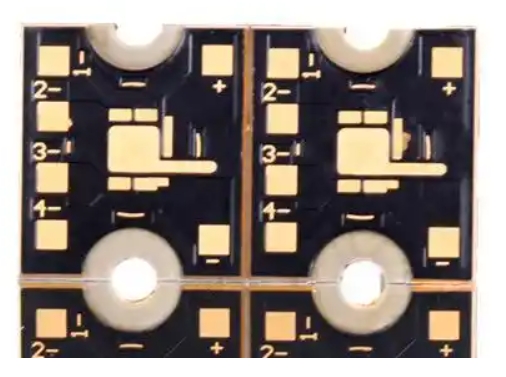
3. Thermal Contact Design
Thermal contact is a critical design parameter for LED PCBs, directly influencing the heat dissipation performance of the LED. The thermal contact can be calculated using the following formula:
Rθ=Tj−TsPRθ=PTj−Ts
where Rθ:Rθ is the thermal contact resistance, Tj:Tj is the junction temperature, Ts:Ts is the substrate temperature, and P:P is the power.
Practical Applications and Industry Use Cases
1. Automotive Lighting
LED PCBs are widely used in automotive headlamps and interior lighting. Their efficient thermal management and reliable circuit design ensure stable operation in harsh environments.
2. Medical Equipment
In the medical field, LED PCBs are used in surgical lighting and medical displays. Their high color accuracy and long lifespan make them a preferred choice.
3. Industrial Lighting
LED PCBs are applied in industrial lighting, including factory lighting and specialized environments. Their high-power and durable design can meet the stringent demands of industrial settings.
Technical Data and Conversion Tables
1. Thermal Conductivity Conversion Table
sheet
| Material Type | Thermal Conductivity (W/m·K) |
|---|---|
| FR4 | 0.3 |
| MCPCB (Aluminum) | 200 |
| MCPCB (Copper) | 380 |
2. Copper Foil Thickness Conversion Table
sheet
| Oz (oz) | Thickness (mm) |
|---|---|
| 1 oz | 0.035 |
| 2 oz | 0.07 |
| 3 oz | 0.105 |
Interactive Question
What is the biggest challenge you face in LED PCB design?
- A. Thermal Management
- B. Circuit Design
- C. Cost Control
- D. Other
Technical Table
sheet
| Parameter | Unit | FR4 | MCPCB (Aluminum) | MCPCB (Copper) |
|---|---|---|---|---|
| Thermal Conductivity | W/m·K | 0.3 | 200 | 380 |
| Applicable Power | W | <10 | 10-50 | 50-100 |
| Common Applications | – | Communication Devices | Automotive Lighting | Industrial Lighting |
Data Visualization
Below is a comparison of thermal conductivity for different LED PCB substrates:
plaintextFR4: 0.3 W/m·K
MCPCB Aluminum: 200 W/m·K
MCPCB Copper: 380 W/m·K
Conclusion
LED PCBs are a crucial component in modern lighting and display technologies. Their design and application require a deep understanding of physical principles, material properties, and thermal management techniques. By selecting the appropriate substrates and optimizing designs, the performance and lifespan of LED devices can be significantly improved.
References
- IPC-7351 Standard: Specifications for copper foil thickness.
- IEEE Transactions on Components and Packaging Technologies: Methods for calculating thermal contact resistance.
- ResearchGate: Research on thermal management for high-power LEDs.
This article provides a comprehensive reference for the design and application of LED PCBs through in-depth technical analysis and practical application cases. Additionally, interactive questions and data visualization enhance reader engagement and understanding.
